Reverse Engineering a Solar Lamp
Part 1 of this post is a write-up of my project for a thermometer with Morse code output. But I was not satisfied with the relatively high power consumption of the circuit, so I decided to use a solar cell to supply the circuit.
A cheap source of solar cells these days are solar garden lamps. You get them for very little money in garden centres and DIY shops. So I went and bought one. The general idea was that such a lamp would not only give me the solar cell, but also a water-tight enclosure, a rechargeable battery and a boost circuit so that all aspects of the power supply would be covered.
And the supply should be more that sufficient for my purposes, since in my thermometer, the LED would only switch on a fraction of the time. By setting the display cycle time carefully, it should be possible to supply the thermometer for 24h per day.
And here it is:

This is a bottom view:

You can see the LED and there is even a switch... When fully assembled, there is a perspex rod screwed to the centre. The rod contains air bubbles in order to disperse the light from the LED.
The Solar Cell
Of course I wanted to know all about that lamp. So I started with the main object of my curiosity: The solar cell. It is immediately obvious that there is some cheating going on. The actual cell area is much smaller than what the large black surface would suggest.
There are four narrow strips of silicon, connected in series. This tells us, that the cell will deliver an open-circuit voltage of about 2 Volts in bright sunlight. This was confirmed by measurement.
There are four narrow strips of silicon, connected in series. This tells us, that the cell will deliver an open-circuit voltage of about 2 Volts in bright sunlight. This was confirmed by measurement.
The short-circuit current of the cell of course depends heavily on the light that shines on it. I measured anything between 1 and 10 mA in the shadow and up to 40 mA in bright sunlight. I made an interesting observation concerning shadow. It seems that it makes a huge difference whether the cell can "see" the sky or not, even if the shadow is otherwise the same. My guess is that this is to do with stray light that arrives on the cells via other parts of the sky.
The Electronics
Here is a view of what is inside the lamp:

Not a lot, really. Not shown is the rechargeable battery. It is a 1.2 Volt / 600 mA NiMH battery according to its label. You can see the two battery contacts. The battery holder is in the bottom part of the enclosure.
Since there isn't much in there and since the PCB has only one layer of copper, drawing the schematic was relatively easy.
But first, let's take a look at the PCB:

There are only five components: An inductor, a capacitor, a diode, the LED and some mysterious component in a transistor-like package (but with 4 pins). Let's have a closer look at it:

On the package it says "YX801". I wasn't able to find a data sheet for this device. But I did find out that it is produced by a Chinese company called shiningic. They seem to produce several ICs which are meant to be used as LED step-up drivers. They don't have a data-sheet download section. But there is a table with some figures - all in chinese. And I think it says that the YX801 is a step-up converter with an input range of 0.9 - 1.3 Volts (matching a single rechargeable cell) and an output current of 5 - 30 mA (matching a single LED). The efficiency seems to be up to 88%. Eventually I found a data sheet for a device named YX8018 by the same company. One of its application circuits matches the one that I extracted from the PCB pretty closely.
The Schematic
This is what it looks like:
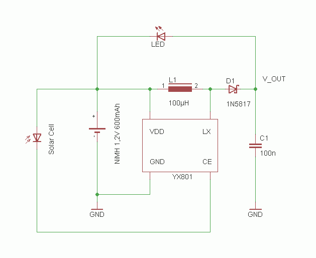
Basically, it is a simple step-up converter. But there are two remarkable points here:
First, the way in which the solar cell is connected. Usually, you would expect it to be connected in parallel with the battery - which it isn't. The solar cell's cathode is not connected to GND, like the battery. Instead, it is connected to pin CE of the converter IC. I found that through this pin I can activate the device (well, not surprisingly). If it is open, the device is active, if it is connected to GND, the converter is off.
With this input, the solar cell doubles as a light sensor. As long as current is produced, CE will deactivate the converter. If it gets dark, there is no current and the IC gets activated.
This gives us a nice possibility to control the LED through a controller port. Set the port to "0" to deactivate the LED, set the port to "Z" to activate the LED.
Second, the LED is not connected between the converter's output voltage and GND. Instead of GND, it is connected to the positive battery terminal. I have absolutely no idea why this is. It reduces the LED voltage by the voltage of the battery, which should have a negative effect on the circuit's efficiency. Perhaps this is a kind of voltage regulation. Vled = Vout - Vbat; so if the battery voltage goes down and Vout goes down, the difference might remain more or less constant. Or perhaps it is done to limit the current through the LED. If you know more, please do leave a comment.
The YX8018 data-sheet shows both possibilities: LED connected to ground and LED connected to Vbat. Perhaps the use of a capacitor on the converter output increases the output voltage over the rated value of the LED?
Further Interesting Measurements
I did a couple of additional measurements to find out, how much current is used by the converter. I must say that the measurements are probably not accurate. I used a standard digital multimeter. And since there are relatively high peak currents, there will be some influence on the measurement of DC currents.
With no load attached, the converter draws about 7mA. This is not negligible. It means it definitely has to de-activated while the LED is off.
The output voltage goes up to 7 Volts with no load attached. So some kind of voltage limiter has to be implemented, in order to avoid frying the microcontroller.
With the existing colour changing LED ("rainbow LED") connected, the circuit draws 15 mA, while the LED draws about 5 mA (Vbat: 1.35 V). This means, the LED doesn't operate at full brightness, because nominal current for these LEDs is 20 mA. On the other hand, this means that even in bad weather, the battery will charge sufficiently to support the LED for several hours. The battery will probably never be fully charged. But if it were, at 600mAh, it could supply the lamp for 20 hours.
One further point I was interested in: What happens if the battery is fully charged, the solar cell is connected in parallel and there is complete darkness. For these condition I measured a "leakage current" of 330µA. Over night (10 hours), this would lead to a total charge of 3,3 mAh lost. Not too bad, I think.
So much for theory. Part 3 of this post details how I patched my thermometer into the lamp circuit.


No part 3? :(
ReplyDeleteAh, thanks for reminding me. I wrote this chapter together with the rest, but wanted to get some long term results. And then I forgot about it...
DeleteSo here it is!
Tom, please help me aquire an ;YX801 led driver 4 pin 1.2 volt, I have had no luck on my own!
ReplyDeleteEMAIL:lwwll3@aol.com & Phone: 954-815-3495
Sorry, I don't have a source for that part. Why don't you buy one of those cheap solar garden lamps? Some are available for under two Euros.
DeleteThe reason for the LED being connected to B+ with 2 batteries is to reduce variation in LED current with battery voltage. There is no regulation built into the IC. Voltage across a white LED is always about 3.2V. The voltage across the inductor when the o/p FET is off is the vol. across the LED (- the battery vol. if the LED is connected to Gnd.). The increase in inductor current & energy when the FET is on is determined by the battery vol. & the ON time which is constant (F~ 200KHz & the FET is on about 58% of the cycle). The energy out is determined by the vol. across the inductor, the current in it & the discharge time. The time is constant, so the energy(W) depends on current & vol., so current will accumulate until Win = Wout. As the voltage difference goes down, the current goes up (& vice versa). The Vol.=Vled-Vbat ~ 3.2V-2.5V~0.7V. As you can see, a small variation in the batttery vol will makes a large change in the current., But if the LED is across the inductor, it is only proportional to the battery voltage.
ReplyDeleteIn their funny translation in one datasheet, I think they are trying to cause the reader to become able to become knowing that:
YX8019 Solar LED driver: Lights the LED in a stable manner off one or two 1.25V batteries.
Sunlight charges the rechargeable battery. To avoid over discharge at night, the LED is automatically switched off when the charge in the battery is low.
The poor chings. They must a struggle as much with our language as we would with theirs.
When I worked it out, it is actually worse than what I said. If all the energy in the inductor is not dumped, there will be a net DC across it, & current will keep accumulating until something limits it (FET drain pulled up, and/or the load vol. pushed up). Even though more energy is dumped due to the increased current, it also draws more energy still, from the battery.
DeleteCorrection to above: Current is proportional to battery vol. squared.
This comment has been removed by the author.
ReplyDeleteThis comment has been removed by the author.
DeleteYou could regulate the o/p vol. with a simple modification: Remove the solar cell from CE & connect it to the battery (through A schottky diode if necessary). connect a small transistor (a BC548 etc) from CE to Gnd. Connect a zener rated at about 0.6V below the reqd. vol.(eg.BZX79C4V3 for 4.9V), from Vout, to Gnd through a resistor. Connect the top of the res. to the trans. base through about a 100ohm res. to protect it. Approx res. value R=.6/Iz The low voltage 79s are specified at Iz=5mA, but have a dynamic resistance spec at 1mA, so that should do for a rough regulator. You could make it adjustable by adding a pot. between the resistor & the zener anode.
ReplyDeleteIf you are regulating down to 3.3V, you will need about a 3.3 or 3.6V zener at 1mA because extra low vol. ones don't have a sharp turn on characteristic.
Tom. Could you please add an 'Edit' option, so changes or updates to comments can be easily made.
DeleteYou could use an ultra-bright green, blue or white LED as a reference instead of a zener. They will drop about 3V at that low a current
Deletewhere is the inductor?
ReplyDeleteok got it i thought it was a resistor
DeleteMuchas gracias por publicar un tema el de YX8018
ReplyDeleteen forma tan completa, ya que el fabricante brinda MUY poca informacion ¡MUCHAS GRACIAS!
Sres Podrian darme datos del YX8018 en ¿ Cual es el Voltaje MAX que puedo administrar al integrado desde una CELDA SOLAR? MUCHAS GRACIAS
ReplyDelete